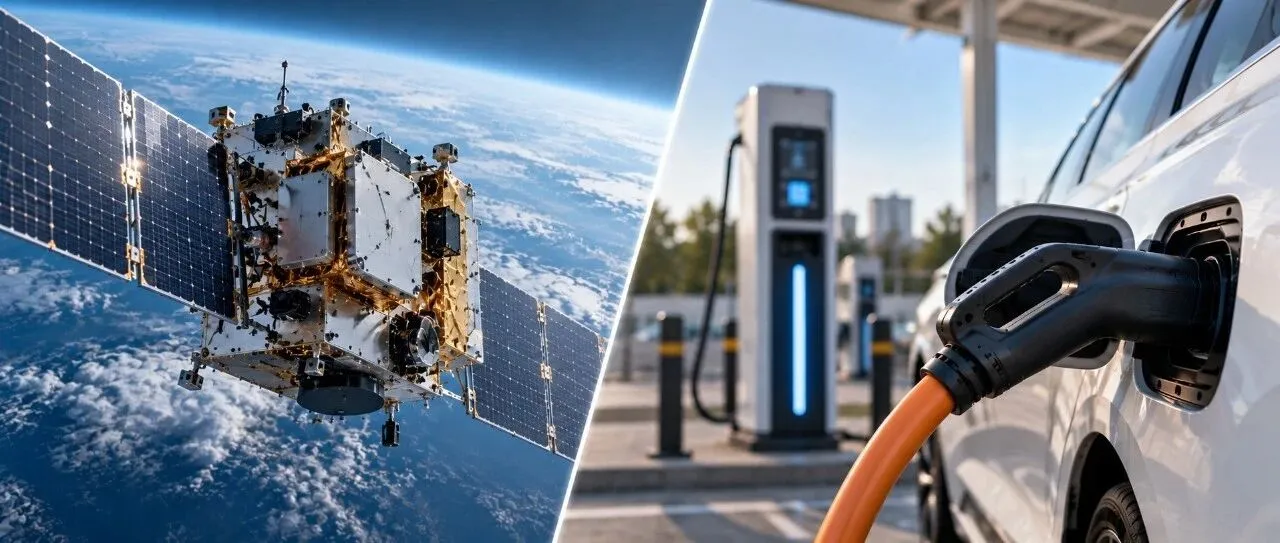
As satellite payloads consume more electricity, power systems must deliver more power to onboard equipment. Electric vehicles seeking shorter charging times must also receive more energy through their charging ports in less time. If the supply voltage stays the same, both demands drive up current.
Higher current increases resistive heating. To control temperature rise and voltage drop, engineers may need thicker conductors, while connectors and switches must be rated for higher currents. The power delivery path becomes heavier and harder to accommodate.
This helps explain why satellite power systems use buses rated at 28V, 42V and 100V, while EVs commonly use 400V and 800V architectures. Understanding these voltage choices requires following the electricity from its source, through the wiring, to the load, and accounting for the entire system.
1. What Does a Device Need from Its Power Supply?
For a device to operate properly, its supply voltage must meet its requirements, and the power supply must be capable of providing the current it needs. Power connects these two quantities and describes the rate at which the device receives electrical energy.
Suppose a device requires a 10V supply and consumes 20W during normal operation. A power consumption of 20W means it receives 20 joules of electrical energy per second. Its operating current is therefore I = P/U = 20 ÷ 10 = 2A. Voltage U is measured in volts, current I in amperes, and power P in watts.
For this device, 10V is the required supply voltage, 2A is the current it draws during normal operation, and 20W is its input power consumption under those conditions. The power supply must maintain the required voltage at the device’s input while continuously supplying 2A. Actual products specify an acceptable input voltage range, which must be checked when selecting a supply.[12]
The current rating on a power supply describes its delivery capability. With a regulated supply rated at 10V and a maximum of 3A, the device in this example still draws approximately 2A. The 3A rating means the supply can deliver more current if needed. When the device changes tasks and its power demand changes, its current draw changes too.[13]
If the supply can deliver no more than 1A at 10V, it can continuously provide only 10W, which is insufficient for the device’s 20W requirement. Once the supply reaches its current limit, its output voltage may fall, preventing the device from starting or causing it to reset during operation.[12][13]
Startup and peak demand must also be checked. Charging capacitors and starting loads may briefly require higher currents. The supply and protection circuits must accommodate these events so that the device can start and continue performing its tasks.[12]
Now consider a different supply rated at 20V and a maximum of 1A. Its maximum output is 20W, numerically equal to the device’s normal power consumption. But the device requires 10V. Connecting it directly to 20V would exceed its operating range and could cause a fault or damage. Both power capability and input voltage must be suitable.
How current changes when the supply voltage changes also depends on the load circuit. For example, connecting a fixed 5Ω resistor to 10V instead of 5V increases its current from 1A to 2A, according to I = U/R. Its power consumption rises from 5W to 20W. Here, increasing voltage increases current because resistance remains constant.
To transmit power at a higher voltage while supplying this device correctly, a suitable voltage conversion stage is needed. A DC/DC converter placed ahead of the device could convert an upstream 20V DC supply into the required 10V DC. The transmission wiring and the device can then operate at different voltages.[14]
The device still requires 10V and 2A, or 20W. Assuming the converter operates at 90% efficiency at this operating point, the upstream supply must deliver 20 ÷ 0.9 ≈ 22.2W, with approximately 2.2W dissipated as losses. Current on the 20V line is approximately 22.2 ÷ 20 = 1.11A, while the converter’s output remains 10V and 2A.[14]
The 20V supply must therefore continuously deliver approximately 1.11A, with additional margin for actual startup and peak requirements. The previously discussed 20V supply limited to 1A would still be unable to sustain the device’s 20W operation, even with a converter.
The transmission voltage has increased, while the device still receives the voltage it needs. Converter selection must account for voltage and current capability on both sides, along with losses and heat dissipation. With this supply arrangement established, the effects of higher voltage on line current and heating can be compared at the same received power.
To transmit the same 5,000W at a lower voltage, more charge must pass through the circuit every second. In other words, current must increase. Conductors, connector contacts and switches all have resistance, measured in ohms. When current flows through them, some electrical energy becomes heat. This resistive loss follows I²R: current in amperes squared, multiplied by resistance in ohms, gives power loss in watts.[1]
For the same conductor at the same temperature, doubling current therefore quadruples resistive heating. Even a small contact resistance can make a connector a critical location for temperature monitoring in a high-current circuit.
Voltage drop also changes. Current flowing through resistance produces a voltage difference across the power delivery path, expressed as ΔU = IR. The voltage reaching the equipment is lower than the supply’s output voltage. Designers must control conductor temperature while ensuring that equipment at the farthest point still receives its specified input voltage under the most demanding operating conditions.
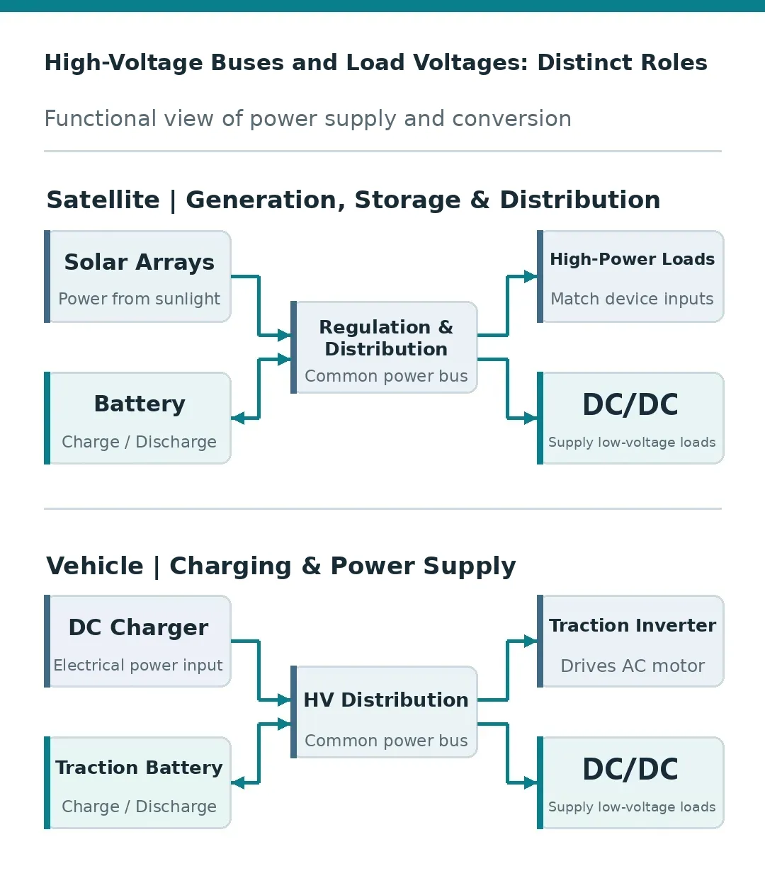
A power bus is a common distribution path connecting power sources and electrical loads. The bus voltage discussed here is the DC voltage used for power distribution. Further conversion takes place inside loads as required.[2]
2. Delivering the Same 5kW: How Much Can Higher Voltage Save?
Consider a transmission example in which the receiving end must obtain 5kW, and the total resistance of the outgoing and return conductors and connection points is 5 milliohms, or 0.005Ω. Set the receiving-end voltage to 28V, 42V and 100V in turn, initially considering only the resistive losses along this power delivery path.
At 28V, current is 5,000 ÷ 28, or approximately 178.6A. Applying I²R gives a line loss of approximately 159.4W. The voltage drop along the path is approximately 0.893V, equivalent to 3.19% of the receiving-end voltage. In addition to delivering 5kW, the supply must provide the 159.4W dissipated as heat.
At 100V, current falls to 50A, line loss is 12.5W, and voltage drop falls to 0.25V. With the same resistance, changing only the transmission voltage produces a substantial difference in current and heating. Figure 1 also includes the 42V case for comparison.
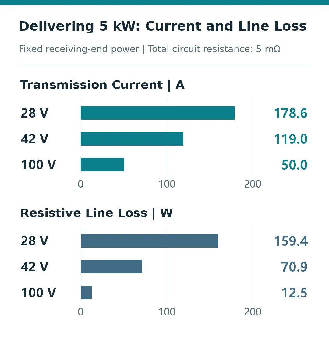
Substituting I = P/U gives line loss = P²R/U². When delivered power and line resistance remain constant, doubling voltage reduces losses to one-quarter of their previous value. This square-law relationship explains why designers of high-power systems are willing to redesign around a higher voltage.
Relative voltage drop follows the same relationship: ΔU/U = PR/U². A smaller relative drop helps control voltage variation at the end of the distribution network. Electronic loads that maintain constant output power often draw more current as their input voltage falls, making the interaction between the supply and load particularly important.
3. Lower Current Can Deliver Greater Efficiency or Lower Weight
The 5mΩ used above includes both conductors and connection points. When selecting different wiring, first consider the conductors separately. Their resistance is R = ρL/A, where ρ is the material’s resistivity, L is the total current path length, and A is the conductor’s cross-sectional area. For the same material, length and temperature, halving the cross-sectional area doubles resistance.
In SI units, resistivity is expressed in ohm-metres, length in metres, and cross-sectional area in square metres, giving resistance in ohms. Where both supply and return use conductors, L includes the full outgoing and return length.
This creates two ways to use the benefits of higher voltage. Keeping the existing conductors mainly reduces line loss, voltage drop and temperature rise. Reducing the conductor cross-section converts part of that benefit into lower weight and less installation space.
Considering only the conductors, doubling transmission voltage and halving conductor cross-section at the same delivered power halves current and doubles conductor resistance. Conductor losses therefore fall to half their previous value. Keeping the original cross-section reduces conductor losses to one-quarter. Losses in connection points and switches must be calculated separately using their respective resistances.
A finished cable also includes insulation, while a wiring harness includes shielding, connectors and mounting hardware. Current-carrying capacity, connector ratings, mechanical strength and manufacturing requirements also limit how far conductor cross-section can be reduced. Engineers therefore assess the mass and temperature rise of the complete power delivery path.
This trade-off is especially important for satellites. Wiring harnesses consume mass and internal space, while heat generated by electrical losses must be removed through structural and thermal control paths. Porsche’s technical explanation of its 800V architecture similarly groups smaller cable cross-sections with lower transmission losses and reduced installation space. The same electrical relationships create comparable physical constraints in both systems.[1][4]
4. What Do Satellites and EVs Gain from Higher Voltage?
For satellites, increasing power usually means continuously transferring more electrical energy among solar arrays, batteries, distribution equipment and payloads. Higher voltage reduces current along the main power paths, making the mass and losses of high-power distribution easier to manage. One historical ESA telecommunications satellite power project used a fully regulated 100V bus, with solar array regulation, battery charging and discharging functions, and power distribution interfaces.[2]
“Fully regulated” means that power regulation stages keep the bus voltage within a controlled range under specified operating conditions. Changes in battery voltage are handled by these stages, giving the loads a controlled input voltage.[2]
A published Chinese power system patent combines two architectures in one system: a fully regulated 28V bus supplies some loads, while a semi-regulated 42V bus supplies others. The specified voltage range of the 42V bus is 38–45.1V.[3]
During discharge, this 42V design connects the battery to the bus through a switch, eliminating a dedicated battery discharge regulator. Once charging reaches the specified voltage, shunt regulation begins limiting voltage, and the charging current gradually decreases.[3]
Removing a discharge conversion stage reduces the associated losses. The trade-off is that bus voltage varies with the battery, so downstream loads must accept the corresponding input range. Different loads can therefore use different bus voltages and regulation methods.[3]
For EV fast charging, power passes through charging equipment, cables and contacts before reaching the traction battery. This path is also constrained by current capability. Delivering 300kW to a DC receiving terminal requires 750A at 400V or 375A at 800V. The former places a greater current burden on the power delivery path.
Now assume a port has a 500A current limit, with sufficient voltage and power capability: 400V corresponds to 200kW, while 800V corresponds to 400kW. Increasing voltage raises the power that can be transferred at that current limit. How closely actual charging approaches this level depends on the operating point permitted by the vehicle, battery and charging equipment at that moment.[4][5]
The terms 400V and 800V describe platform voltage classes. Actual battery pack voltage changes with state of charge and operating current, and DC charging equipment must adjust its output to match the pack. The charging power displayed by the vehicle reflects the combination of voltage and current at that moment.[4][5]
5. What Happens to Equipment and Battery Cells When Bus Voltage Rises?
A satellite’s digital circuits, sensors and controllers each require suitable operating voltages. When the main bus rises to 100V, DC/DC conversion at the equipment input can supply the voltages needed by internal circuits. This separates main power transmission from local load supply.[2]
Some loads require higher voltages themselves, allowing the main bus voltage to be selected accordingly. ESA has studied a high-voltage solar array operating at approximately 350V to explore directly powering electric propulsion. One objective was to reduce the need for intermediate voltage step-up stages.[8]
EVs use a similar division of functions. The traction battery supplies the drive inverter, which converts DC into the AC required by the motor. Low-voltage equipment receives power through appropriate converters.[4][11] The battery management system monitors cells and manages charging and discharging, while high-voltage distribution and protection devices connect, disconnect and monitor the relevant circuits.[10]
Even when main circuit current falls, the current through each battery cell must still be examined. Rearranging the connections of the same cells illustrates the relationship between pack terminal current and individual cell current.
Cells can be connected in series or parallel. Connecting identical cells in series adds their voltages; connecting identical series strings in parallel shares the total current among them. Increasing the number of series-connected cells is one way to raise pack voltage. Total energy also depends on the total number of cells and the energy each cell can store.
Consider an ideal example using eight identical cells, each rated at a nominal 3.6V and 5Ah. A two-series, four-parallel arrangement, or 2S4P, produces 7.2V and 20Ah. A four-series, two-parallel arrangement, or 4S2P, produces 14.4V and 10Ah. Multiplying the nominal ratings gives 144Wh for both configurations. Ampere-hours describe charge capacity, while watt-hours describe energy. Rearranging series and parallel connections changes both pack voltage and ampere-hour capacity.
Assume both configurations deliver 144W at their nominal voltages, with no losses and equal current sharing among parallel branches. The first has a pack terminal current of 20A, divided among four branches, so each cell carries 5A. The second has a pack terminal current of 10A, divided among two branches, so each cell still carries 5A. Pack terminal current has halved, while individual cell current remains unchanged.
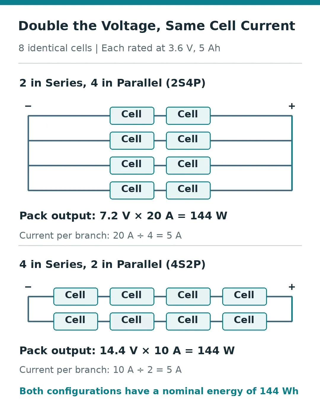
If each cell has the same internal resistance, total resistive heating within the cells can also be identical in these two configurations. The external wiring benefits of higher voltage must be calculated separately from current, internal resistance and temperature inside the battery.
During charging, current reverses direction, but the same relationships apply: series-connected cells carry the same current, while parallel branches share current. The actual charging operating point must be determined using cell voltages and conditions at that time.
Battery charging rate is commonly expressed as a C-rate, the ratio of charging current to rated ampere-hour capacity. Charging a 5Ah cell at 5A, for example, corresponds to 1C. Available EV charging power is also constrained by temperature, state of charge and vehicle control strategies. Assessment therefore requires examining how power changes throughout a charging session and how long charging actually takes.[5]
6. Where Do the Additional Costs of Higher Voltage Appear?
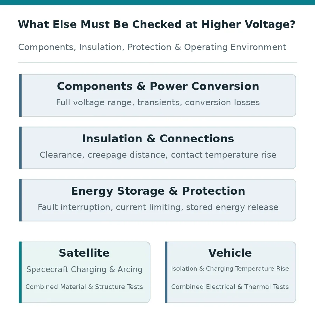
As main circuit current decreases, high-voltage components and insulation structures must withstand higher voltages. Power switches, connectors and capacitors must be selected for actual operating voltage, current and switching transients. Voltage spikes caused by circuit inductance must also be included in the design.
Absolute maximum ratings in component documentation define the limits a device can withstand for voltage and other parameters. Normal operation must remain within the specified operating range, with margin for voltage spikes caused by switching.[12]
Insulation design considers where voltage is applied, the distance between adjacent conductors, and surface conditions. Clearance is the shortest distance through air between two conductive parts. Creepage distance is the shortest path between them along the surface of solid insulation. Vehicles must also account for how vibration, contamination and moisture affect insulation and connection reliability.[9]
Galvanic isolation is commonly used between high-voltage circuits and low-voltage control circuits. Signals or energy pass through isolation components while a direct conductive path is blocked. Inverter gate drives, measurements and high-voltage insulation monitoring must work with the vehicle’s overall protection strategy. TI’s automotive materials address isolated gate driving, battery management and onboard insulation monitoring.[6][10]
Fault interruption also changes. DC current lacks the periodic natural zero crossings of AC, so mechanical switches must control the arcs that may form when opening a circuit. Energy stored in a capacitor is E = ½CU², where C is capacitance in farads, U is voltage across the capacitor in volts, and E is energy in joules. At the same capacitance, doubling voltage quadruples stored energy.
Contactors, current-limiting devices and discharge circuits must be designed around fault currents and stored energy. Cable savings from higher voltage must be weighed against the additional mass and losses of these devices, insulation structures and conversion stages.
Satellites face the added effects of the space environment. The surrounding plasma contains free electrons and ions that can exchange charge with exposed surfaces, giving solar arrays and the spacecraft body electrical potentials relative to their surroundings. Local potential differences, exposed conductor edges and insulating surface conditions all influence discharge behavior.[7]
Once a primary arc occurs on a solar array, adjacent circuits may continue supplying energy to the discharge path, producing a more destructive sustained arc. NASA’s high-voltage solar array tests used simulated plasma, electrical biasing and voltage differences between strings to observe both types of discharge. The focus was on how specific materials and structures behaved under operating conditions, rather than on a single bus voltage rating.[1]
The ESA high-voltage solar array study also used simulations and test coupons to investigate interactions with space plasma and electric propulsion plumes, assessing the environmental suitability of materials and structures.[8]
7. How Do Engineers Choose a Voltage and Verify the Benefits?
Design begins with mission power requirements. Continuous load demand, peak power and which devices operate simultaneously all affect current along the distribution paths. Engineers then establish wiring lengths, allowable voltage drops, connector capabilities and cooling conditions. Each candidate voltage is paired with actual cables and converters to calculate system mass and losses.
Battery systems must also be checked across their full operating voltage range. At low state of charge, maintaining the same power often requires higher current. At high state of charge and during switching transients, voltage stress may be greater. Load input ranges, component voltage ratings and current capabilities must be checked separately under these conditions.
Testing can begin by measuring voltage and current at both the supply and load ends to determine power delivery losses, followed by temperature-rise measurements on conductors, contacts and switches. Load steps, startup inrush and specified fault conditions are then introduced to check bus stability, correct protection operation and which branches are affected by a fault.
High-voltage satellite solar arrays also require verification of surface charging and discharging in simulated space environments appropriate to the mission. EV fast-charging tests must record voltage, current and temperature rise at different temperatures and states of charge, along with the time required for a complete charging session. The final comparison concerns the performance of the entire system under equivalent task conditions.[1][5][8]
Low-power missions with short distribution paths can continue using established low-voltage architectures. As power demand grows and wiring becomes more costly in mass and space, higher voltage becomes more likely to deliver system-level benefits. Satellites and EVs differ in power levels, environments, service lives and available components, so their final voltage choices also differ.
As power increases, raising voltage can ease the cable, heating and voltage-drop problems associated with high current. Further increases in voltage bring additional requirements for insulation, conversion, protection and environmental compatibility. The appropriate voltage is an operating point selected by weighing these costs together and verifying the result through testing. Satellite buses and automotive high-voltage platforms follow the same approach to these trade-offs.
These trade-offs also matter when defining a custom satellite or payload. STARPATH GLOBAL helps international customers access China’s satellite, payload and assembly, integration and testing capabilities. Customers can discuss their requirements with the team to align power demand, mass limits and operating conditions with suitable supplier options.
References
[1] T. Schneider et al., High Voltage Solar Array Arc Testing for a Direct Drive Hall Effect Thruster System, NASA conference paper, March 1, 2004, NTRS 20040111032.
[2] European Space Agency, SRU @BUS, historical telecommunications satellite power system project documentation, page status date: August 10, 2007.
[3] DFH Satellite Co., Ltd., A High-Power and High-Efficiency Satellite Power Supply System Based on High-Voltage and Low-Voltage Dual Buses, published patent CN106410936A, February 15, 2017.
[4] Porsche, Taycan: The Glossary, official technical explanation, accessed October 15, 2026.
[5] Australian Government energy website, Electric Vehicle Charging Equipment, accessed October 15, 2026.
[6] Texas Instruments, How to Design High-voltage Systems with Higher Reliability While Reducing Solution Size and Cost, SSZT071, June 2022, “EV Applications” section.
[7] NASA/NESC, Understanding the Potential Dangers of Spacecraft Charging, January 12, 2017.
[8] European Space Agency, High-Voltage High-Power Solar Array For Exploration Missions, research results overview, February 23, 2018.
[9] Texas Instruments, TI Precision Labs—Isolation: What Are Creepage and Clearance?, public technical training, March 31, 2020, accessed October 15, 2026.
[10] Texas Instruments, HEV/EV Battery-Management System (BMS), official automotive battery management system design materials, accessed October 15, 2026.
[11] Jason Cao, Reduce EV Cost and Improve Drive Range by Integrating Powertrain Systems, Texas Instruments, SSZT170, May 2021.
[12] Texas Instruments, LM2596 SIMPLE SWITCHER Power Converter, datasheet SNVS124G, revised March 2023, Sections 7.1, 7.3, 8.3 and 9.1.1, accessed October 17, 2026.
[13] Keysight, How to Characterize Power Supply Current Limits, official technical explanation, accessed October 17, 2026.
[14] Frank De Stasi, Demystifying Input Supply Current in DC/DC Regulators: From Shutdown to Full Load, Texas Instruments, SLYY189, May 2020, p. 5, accessed October 17, 2026.