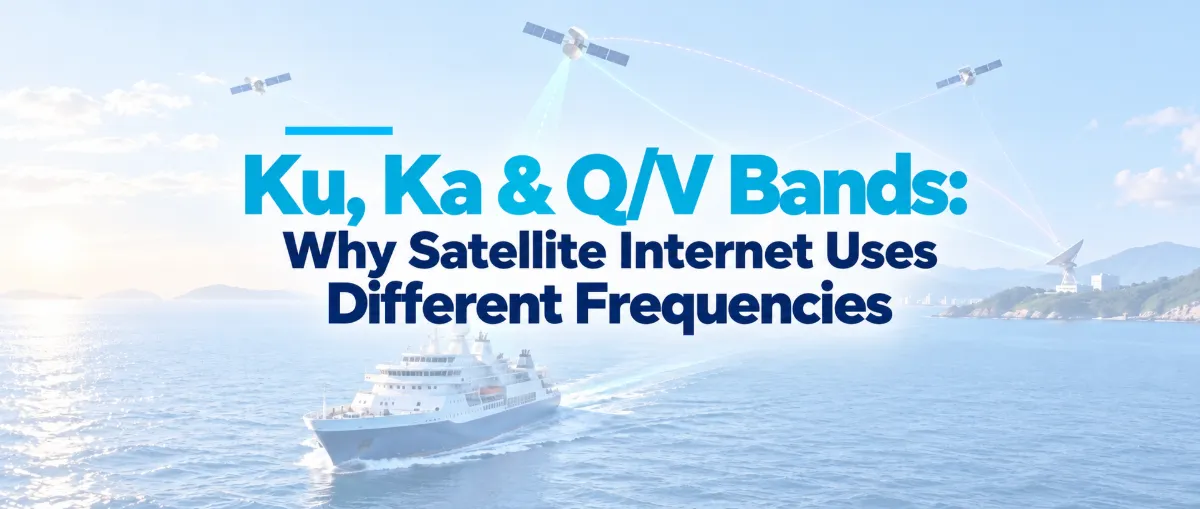
A ship is at sea. A phone connects to the vessel’s satellite terminal, and a webpage image finally appears. The image first travels from the terrestrial internet to a gateway, passes through a satellite and then reaches the ship. Following this transmission path helps explain why Ku, Ka, Q and V bands perform different roles.
A gateway connects the satellite network to the terrestrial internet; a feeder link connects the gateway and the satellite; and a user link connects the satellite and the terminal. A user beam generated by a satellite antenna covers a particular area, within which users share the available capacity. Ku, Ka, Q and V indicate the frequency ranges occupied by the radio waves.
How Does a Webpage Image Travel Through a Satellite?
Consider a ship accessing the internet by satellite. A server on shore sends an image into the operator’s terrestrial network. The data travels over fiber to a satellite gateway, whose antenna transmits it to the satellite. The satellite then sends it to the terminal aboard the ship. Only after the terminal passes the data to the vessel’s router does the image reach the phone.[12]
A user link is the radio connection between the satellite and a user terminal. In this example, the satellite terminal consists of the antenna and communications equipment installed on the ship. The connection between the phone and the ship’s onboard Wi-Fi is a separate part of the network. The terminal both receives data sent by the satellite and transmits requests back to it. Fixed residential terminals operate on the same basic principle, although their physical design and pointing method may differ.
A feeder link carries aggregated traffic between a ground gateway and a satellite. Here, “feeder” refers to the transport of communications traffic, not the satellite’s electrical power system. Each of many user terminals may consume only a small share of capacity, but the gateway must aggregate large volumes of traffic in both directions. Feeder links therefore often need to support much higher total throughput.[12]
Two sets of directional terms are frequently confused. When a user downloads a webpage, the gateway-to-satellite transmission is an uplink, while the satellite-to-user transmission is a downlink. When the user uploads a photograph, the user-to-satellite transmission is the uplink, while the satellite-to-gateway transmission is the downlink. Uplink and downlink are defined solely by the direction in which the radio wave travels relative to the satellite. They do not correspond directly to whether someone taps “upload” or “download” on a phone.
Web browsing also illustrates that traffic is often asymmetrical. A user’s request for a webpage may be very small, while the images and videos returned by the server can be much larger. A network therefore plans forward capacity from the gateway to users separately from return capacity from users to the gateway. Livestreaming and remote operations can substantially increase return-path demand. Any comparison between transmission rates must first establish which direction is being discussed.
What does the satellite do in the middle? A transparent transponder receives a signal, filters it, converts its frequency, amplifies it and retransmits it. A regenerative payload can also demodulate, process and remodulate the signal. The information continues toward the user, but the radio-frequency carrier transporting it may change frequency. The gateway and user sides can therefore operate in different bands. If the system includes inter-satellite links, the data may first pass between satellites before being routed through another gateway.[8][12]
Is a Gateway a Device, a Ground Station or an Internet Access Point?
A ground gateway is generally a ground station and associated network infrastructure connected to the terrestrial backbone. It includes fiber links and routing equipment, modulation, demodulation and coding systems, frequency upconverters, power amplifiers and large-aperture antennas, as well as receivers, monitoring equipment and operations systems. Large networks also require traffic coordination and failover between gateway sites. The gateway is the boundary between the satellite network and the terrestrial network.[8][12]
On the forward path, the gateway’s network-control system determines where the traffic should go. Baseband equipment places the bits into frames, adds error-correction coding and modulates the signal. An upconverter shifts the signal to the designated transmission frequency, a power amplifier provides the required radio-frequency power, and the antenna directs the signal toward the satellite. Beams and time-frequency resources are assigned by the network’s scheduling system.
On the return path, the antenna receives the signal. A low-noise receive chain, downconverter, demodulator and decoder then reconstruct the data packets from the radio signal and return them to the terrestrial internet.[8]
A gateway’s transmitting capability is often characterized by its equivalent isotropically radiated power, or EIRP. This indicates the effective signal strength produced in the target direction after accounting for amplifier output, feeder losses and antenna gain. Receiving capability is commonly measured by G/T, the ratio of antenna gain to system noise temperature. A large antenna alone is not enough: high noise in the receive chain can still overwhelm a weak signal. These two figures help constrain the link budgets for the feeder uplink and downlink, respectively.[18]
A gateway can accommodate large antennas, high-power equipment and reliable fiber connectivity. It must also match the available spectrum, the interfaces between the antenna and satellite payload, the waveform, satellite visibility, switching capacity and terrestrial backhaul. Determining how many beams one gateway can support requires checking each of these interfaces.
Because low Earth orbit satellites move quickly across the sky, their networks must also manage handovers between satellites and ground stations. Geostationary systems are more concerned with long-term site availability and the aggregation of high-capacity traffic.
Once a system creates large numbers of user beams, the gateway may become the first bottleneck. The user side may be able to carry many simultaneous data streams, but network growth will be constrained if the feeder capacity between the gateway and satellite does not expand accordingly. ESA has therefore explored moving feeder links into Q/V band or deploying separate feeder-link satellites that aggregate traffic through inter-satellite links. Both approaches are intended to expand this backbone channel.[12]
How Many Users Does One User Beam Serve?
A beam is the spatial coverage pattern created when an antenna concentrates electromagnetic energy in a particular direction. When projected onto Earth, it becomes a service area. A relatively narrow “spot beam” can concentrate coverage on a city, an air route or a section of ocean. Unlike an administrative boundary on a map, the edge of a beam is not abrupt: signal strength generally declines gradually from the center toward the perimeter.
A user beam is the coverage beam through which a satellite communicates with terminals. One beam can serve many terminals, and one satellite can generate multiple beams. The Hylas-1 payload described by ESA used eight Ka-band spot beams to serve different parts of Europe, reusing spectrum across geographically separated beams.[13]
A terminal establishes a user link with the satellite while it is within the user beam’s coverage. Many terminals in the same area may be waiting for service at the same time. The network allocates capacity among them through time slots, frequency resources, scheduling, modulation and coding.
For that reason, a statement such as “this beam has a capacity of 1 Gb/s” describes the combined information rate that the beam can carry. It does not mean that every terminal will consistently receive 1 Gb/s. Users in congested periods, at the edge of the beam or under rainy conditions may receive different levels of service.
Why are additional beams useful? If two sufficiently separated areas do not create unacceptable interference, the network can reuse the same spectrum in both locations—much as two different districts can each have a road with the same name. Reusing the same frequency range in separated beams increases the satellite’s total simultaneous capacity.
If adjacent beams reuse frequencies too aggressively, however, they can interfere with one another. Antenna radiation patterns, frequency allocation, polarization planning and techniques such as precoding are needed to control that interference.[13][15]
There are therefore three distinct layers: the terminal is the equipment on the ground; the user link is the connection between that terminal and the satellite; and the user beam is the area covered by the satellite antenna. Estimating the speed available to an individual customer also requires information about concurrency, busy-hour traffic, terminal location and service level.
Ku, Ka, Q and V Are Frequency Bands With Different Strengths
Frequency describes how many times an electromagnetic wave oscillates each second. One gigahertz is one billion cycles per second. Wavelength is approximately equal to the speed of light divided by frequency. A 14 GHz signal has a wavelength of about 2.1 centimeters, a 30 GHz signal about 1 centimeter, and a 50 GHz signal about 6 millimeters.
The carrier frequency indicates where the radio signal is located in the spectrum. Bandwidth describes the width of the spectrum allocated to the communications signal. They are not the same number.[1][2]
Ku, Ka, Q and V are conventional names for frequency ranges in the microwave and millimeter-wave spectrum. In commonly used radar-band nomenclature, Ku lies below K band, while Ka lies above it. The precise boundaries assigned to Q and V also vary among references.
In the satellite industry, links using approximately 20 GHz for space-to-Earth transmission and 30 GHz for Earth-to-space transmission are commonly described together as Ka-band links, even though some general radar-band tables define a different starting point for Ka band. Engineering documents must therefore specify the actual frequency in gigahertz, the direction of transmission and the applicable service authorization.[1][2][4]
Ku band commonly uses frequencies around 12 GHz for space-to-Earth downlinks and 14 GHz for Earth-to-space uplinks. Its applications include television broadcasting, VSAT networks, some mobile broadband services and user access for low Earth orbit systems.
Ku band benefits from a mature equipment and service ecosystem. Under comparable conditions, its rain attenuation is generally easier to manage than that of higher-frequency bands. The U.S. Federal Communications Commission’s 2017 authorization for OneWeb included space-to-Earth operations at 10.7–12.7 GHz and Earth-to-space operations at 14–14.5 GHz, providing a publicly documented example of Ku-band operating frequencies.[3][7]
Ka band commonly uses frequencies around 20 GHz for downlinks and 30 GHz for uplinks. It can be used for either user links or gateway connections. Ka band is widely employed by high-throughput satellites because its available spectrum, narrow beams and capacity for frequency reuse create additional design options. At the same time, terminal pointing, radio-frequency components and rain-fade mitigation become more demanding. Whether Ka band is assigned to user or feeder links depends on the system’s spectrum plan.[4][8]
Q/V bands are often considered for high-capacity feeder links. A gateway may transmit toward the satellite in V band at approximately 50 GHz, while the satellite transmits toward the gateway in Q band at approximately 40 GHz.
ITU-R S.1782-1 presents one frequency plan using Ka band on the user side and Q/V bands on the gateway side. It assigns 47.2–50.2 GHz and 50.4–51.4 GHz to gateway uplinks and 37.5–40.4 GHz to downlinks toward the gateway. Actual frequency selection must also account for regional service allocations, coordination requirements and licensing.[5][17]
Gateways are concentrated at a limited number of locations and can use large antennas, making them better suited to difficult high-frequency links. User terminals are numerous and geographically dispersed, with tighter constraints on cost and antenna size, so they more commonly use the relatively mature Ku or Ka bands.
ESA’s Q/V-Feed project has completed the design, manufacture and radio-frequency testing of an engineering model feed system. Foresig has conducted trials involving channel prediction and adaptive techniques, while QUBE is advancing the development of Q-band power-amplifier chips. These projects address the feed system, link control and power-amplifier components, respectively.[6][10][11]
How Can 500 MHz Become 1 Gb/s?
Consider a simplified example. Suppose a beam has 500 MHz of available channel bandwidth around a particular operating frequency. The center frequency might be in Ku, Ka or another band, but the 500 MHz figure describes the width of the radio channel. A road may have a different address in each city, but the number of vehicles that can travel side by side depends first on the number of lanes.
The next question is how much useful information each hertz can carry per second. Assume that the waveform has a net spectral efficiency of 2 bit/s/Hz. This figure already accounts for physical-layer overhead such as modulation, forward-error correction, frame headers and pilot signals, as well as the spectral effects of roll-off and guard bands. ETSI’s DVB-S2X comparisons calculate information bits per second per hertz using these factors, rather than simply counting how many bits each symbol can represent.[14]
Take modulation and coding as an example. A QPSK symbol can represent two bits. With a forward-error-correction code rate of 3/4, approximately 1.5 information bits per symbol remain after coding redundancy is deducted. Frame headers, pilot signals and the additional spectrum occupied by the signal further affect the final bit/s/Hz figure.
Higher-order modulation allows each symbol to carry more bits, but it requires a cleaner received signal. Selecting a modulation and coding scheme is therefore a tradeoff between throughput and resistance to noise.[14]
The illustrative information rate is:
500,000,000 Hz × 2 bit/s/Hz = 1,000,000,000 bit/s
That equals 1 Gb/s. The hertz units cancel out, leaving bits per second. This calculation simply converts the width of the available spectrum into the information rate that can be supported under the assumed link conditions.
Expressed in bytes, 1 Gb/s is theoretically equivalent to 125 MB/s. Because one byte contains eight bits, confusing bits with bytes produces an eightfold difference.
Why must the result be qualified as applying under particular “link conditions”? The transmitter maps bits onto distinguishable radio-wave states, and the receiver must identify those states amid noise and interference. When signal quality is good, the system can use higher-order modulation and less error-correction redundancy. When rain weakens the signal, it may switch to a more robust modulation and coding scheme.
Using the same illustrative figures, if spectral efficiency falls to 1 bit/s/Hz, the same 500 MHz of bandwidth supports only about 0.5 Gb/s.[8][14]
Only after that calculation can the network estimate how much speed an individual user may receive. The 1 Gb/s figure is the combined information rate of the entire example beam or channel. If 100 terminals simultaneously share it at full load under identical conditions, a simple equal division would provide about 10 Mb/s per terminal.
Actual networks use dynamic scheduling. The proportion of active terminals, protocol overhead, retransmissions and congestion all affect the speed experienced by each user.
Now consider the entire satellite. Suppose four widely separated beams each reuse the same 500 MHz of spectrum and each maintains a spectral efficiency of 2 bit/s/Hz. The combined user-side capacity would be 4 Gb/s. But if all of that traffic must pass through a feeder channel with an aggregate capacity of only 2 Gb/s, total end-to-end throughput will be constrained first by the feeder side.
Onboard processing, the terrestrial backbone and service policies can also affect the final capacity. The feeder-link bottleneck described by ESA is precisely the challenge of matching backbone capacity to user-side capacity.[12][13]
Feeder capacity can be expanded by adding gateways, allocating more spectrum to feeder links or improving the spectral efficiency of each feeder connection. Each option affects site selection, antennas, power amplifiers, the satellite payload and frequency coordination.
If multiple user beams depend on the same gateway, that gateway’s satellite visibility, local weather and terrestrial backhaul also become part of the capacity calculation.[12]
Comparisons of satellite capacity must distinguish among a single carrier, a single beam and the aggregate capacity of the entire spacecraft. They must also identify the transmission direction, establish whether the gateways can accommodate the user-side traffic, and state the target weather and busy-hour conditions. Only then is it possible to understand which layer of service a headline Gb/s figure actually describes.
Why Do Higher Frequencies Bring Both Opportunities and Challenges?
Higher-frequency bands often provide opportunities to access wider blocks of spectrum, provided that their use complies with local service allocations, system-coordination requirements and licensing.
In the previous example, the data rate was determined by the allocated 500 MHz of bandwidth, the prevailing signal-to-noise ratio, the selected modulation and coding, and the interference environment. Moving a system to Q band requires all of these factors to be recalculated. The carrier frequency cannot simply be replaced while everything else remains unchanged.[8][14]
For antennas with similar physical apertures and efficiencies, increasing the frequency shortens the wavelength, generally increasing antenna gain and narrowing the beam. This helps concentrate energy and create more small-area coverage beams, but it also demands more accurate pointing and tracking.
A ship rolls with the sea, an aircraft changes direction, and both the terminal and satellite may be moving relative to one another. Pointing errors in a mechanically steered or phased-array antenna translate directly into link losses. Engineers therefore hold variables such as antenna aperture, gain or transmit power constant when evaluating the effects of a frequency change.[8]
High-frequency Earth-to-space links must also pass through the atmosphere. Attenuation caused by rain, clouds and atmospheric gases varies with frequency, rainfall intensity, elevation angle, location and the percentage of time being considered. Under common Earth-space operating conditions, designing Q/V-band links for rainy weather is more demanding than designing Ku-band links.
A link budget must examine the transmit power, antenna gain, propagation losses, receiver noise and required signal-to-noise ratio at each stage, while preserving sufficient margin to meet the agreed availability target.[9]
Gateway sites can be placed in relatively dry regions, and a network can operate multiple sites. When heavy rain affects one gateway, the network may shift feeder traffic to another site if sufficient capacity and switching resources are available. ESA has also discussed multi-gateway architectures and adaptive coding and modulation.
Changing gateways, however, only addresses rainfall at the gateway site. If heavy rain is directly above the ship’s terminal, the user link must still rely on its own link margin, power control or reduced data rate.[9][16]
Engineers calculate availability using long-term rainfall statistics, the target location and an agreed percentage of time. Improving availability generally requires more power, a larger antenna aperture, backup gateway sites or additional spectrum resources.
The peak clear-sky rate and the minimum rate that can be maintained during heavy rain may therefore be designed and tested separately within the same network.[9]
Putting Frequency Selection Back Into the Complete Network
Engineers generally begin by defining the service: where coverage is required, how many terminals will use the network, how much busy-hour capacity each terminal needs, and how much service unavailability is acceptable.
They then examine the relevant regional frequency allocations and coordination conditions before dividing the capacity requirements among the user side, feeder side and terrestrial network. User-beam design, gateway numbers, antenna aperture, onboard amplifiers, power supply and thermal control are all shaped by this overall capacity calculation.
Separate link budgets are then prepared for the forward and return paths. Engineers check whether each link closes under clear-sky conditions, what rate it can maintain during rain fade, and how much margin remains at the edge of a beam. Low Earth orbit systems must also account for satellite visibility windows and handovers between ground stations.
Individual radio-frequency units are tested for gain, noise, out-of-band emissions and intermodulation. Satellite-level tests assess beams, polarization and pointing, while ground tests verify gateway switching. Finally, terminals are connected through the entire system to run end-to-end internet services.[8][9]
Frequency selection begins by identifying which parts of the system a band will connect. Engineers must then determine whether user-beam capacity and gateway feeder capacity are properly matched, before evaluating what level of service can be delivered during rainy weather and busy periods in the target region.
Only when the equipment, beams, links and capacity are connected into one complete architecture do Ku, Ka and Q/V become an operational satellite communications system.
As satellite internet systems expand, frequency planning must be matched with the right spacecraft, communications payloads, ground systems and AIT capabilities. China’s growing commercial space capacity is bringing more competitively priced options to the global market, and international customers can contact STARPATH GLOBAL to evaluate solutions aligned with their network architecture, technical requirements and budget.
References
[1] NASA, What Are the Spectrum Band Designators and Bandwidths?, 2018; origins of frequency-band letters and commonly used ranges.
[2] NASA Science, Chapter 6: Electromagnetics, Page Three; variations in Q/V-band boundaries and their use in satellite communications.
[3] U.S. Federal Communications Commission, FCC 17-77, 2017; examples of Ku- and Ka-band uplink and downlink frequencies in OneWeb’s U.S. market-access authorization.
[4] ESA, Low Cost Precision Manufacturing RF Passive Hardware; an example of a Ka-band radio-frequency link operating at approximately 20/30 GHz.
[5] ESA, Uplink Power Control Method and Apparatus for Satellite Communications Networks; Q-band downlinks at approximately 40 GHz and V-band uplinks at approximately 50 GHz.
[6] ESA, Q/V-Feed; division between Q/V-band gateway feeder links and Ka-band user spectrum, including the engineering model.
[7] ITU-R Report M.2460-0, 2019, Table 2 on printed page 15; examples of satellite applications using Ku, Ka, Q and other frequency bands.
[8] NASA, State-of-the-Art of Small Spacecraft Technology, Section 9.0, Communications; frequency bands and design considerations, radio-frequency conversion, high-frequency links, pointing and antenna tradeoffs.
[9] ITU-R Recommendation P.618-14, 2023; current propagation prediction methods for rain, cloud and atmospheric-gas effects on Earth-space links.
[10] ESA, Foresig; a test platform for channel prediction and adaptive technologies using Ka-band user links and Q/V-band feeder links.
[11] ESA, QUBE; development of power-amplifier chips for Q-band active antennas.
[12] ESA, Multiple Access Telecom Reconfigurable Intersatellites; user links, feeder links, gateway-capacity bottlenecks and frequency reuse in typical multibeam systems.
[13] ESA, Hylas-1 Payload; eight Ka-band spot beams and spectrum reuse across different geographic areas.
[14] ETSI TR 103 886 V1.1.1, 2025, Section 5.5.1 and Table 37; information-bit spectral efficiency accounting for coding, frame overhead, pilot signals, roll-off and guard bands.
[15] ESA, Joint Transmitter Signal Processing in Multi-Beam Satellite Systems; transmission of data to multiple terminals within a spot beam and interference among co-frequency beams.
[16] ESA, Multibeam Satellite Communication System and Method; publicly described approaches involving gateway switching, adaptive coding and modulation, and Q/V-band feeder links.
[17] ITU-R Recommendation S.1782-1, 2019; an example frequency plan using Ka-band user links and Q/V-band feeder links for broadband satellite internet.
[18] ITU, Handbook on Satellite Communications, Third Edition, 2002; definitions of Earth-station EIRP and the receiving figure of merit G/T in link-budget calculations.