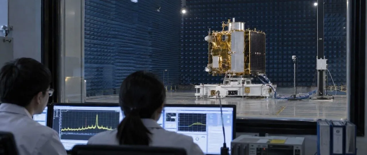
The onboard computer runs normally on its own. The receiver passes its sensitivity test. The power controller, reaction wheel driver and transmitter each have a test report. Then engineers install them in the same satellite, and the results change: the receiver’s noise floor rises when the computer is heavily loaded; a sensor begins producing erratic readings when a reaction wheel moves; and switching on a transmitter reduces the margin on another receive link.
None of the units is necessarily faulty. Once they share power, cables, structure and space, circuits that were previously separate become a new electromagnetic system.
That is why a satellite needs electromagnetic compatibility testing after integration. Unit-level tests ask whether each device meets its interface requirements. Whole-spacecraft testing asks whether the combined system can still carry out its mission.
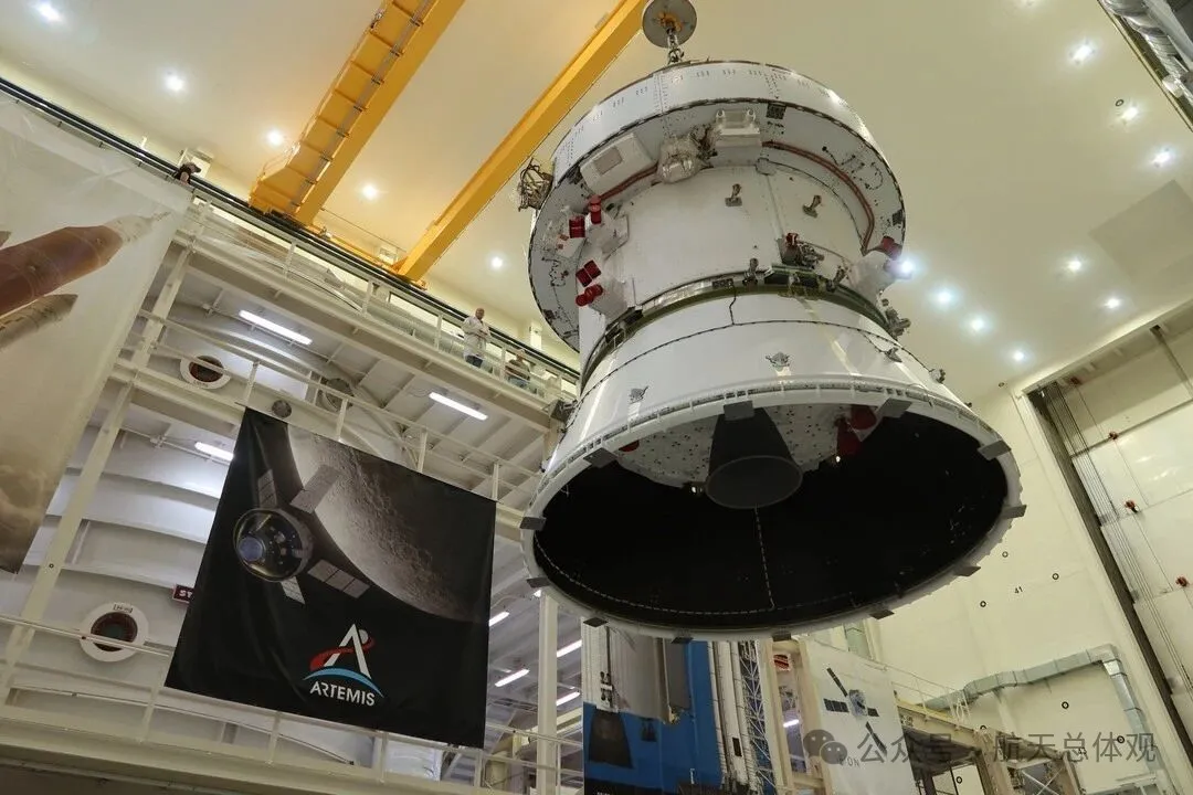
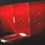
The integrated Orion crew and service module for NASA’s Artemis II mission returned to the Final Assembly and System Testing cell on April 27, 2024, after electromagnetic compatibility and interference testing. Credit: NASA/Amanda Stevenson.
EMC asks whether equipment can coexist
Electromagnetic compatibility, or EMC, has two parts in the IEC definition: equipment or a system must operate satisfactorily in its electromagnetic environment without introducing unacceptable electromagnetic disturbance into that environment.[1]
Two related terms are easy to confuse. An electromagnetic disturbance is a phenomenon that could degrade equipment performance. Electromagnetic interference, or EMI, is the performance degradation caused by such a disturbance.[2] Switching noise may appear on a spectrum without causing trouble. It becomes interference when it produces receiver errors, sensor drift or a computer reset.
Compatibility therefore does not mean the absence of noise. Switching power supplies must switch, digital circuits must change state, motors must commutate, and radios are designed to transmit. The engineering goal is to establish conditions under which they can coexist: emissions remain sufficiently low, equipment withstands the disturbances it encounters, and critical functions meet their requirements in specified operating modes.
Interference usually involves three elements: a source, a coupling path that carries its energy, and a susceptible device. A remedy can address any of the three by reducing emissions at the source, interrupting the path or making the affected device less susceptible.
How interference travels through a satellite
A satellite has no shortage of potential sources. DC/DC converters switch rapidly to change voltage and generate harmonics as well as a fundamental switching frequency. Processors, memory and high-speed interfaces produce clock signals and sharp data edges. Reaction wheels, pumps, valves and deployment mechanisms draw rapidly changing drive currents. Telemetry, tracking and command transmitters, high-rate downlink transmitters and payload transmitters are intentional sources of stronger radio-frequency emissions.
The same spacecraft also carries highly sensitive equipment. Receivers must detect weak signals against a noise background. Star trackers and scientific payloads can contain low-noise analog front ends. Temperature and attitude sensors must resolve small changes. A spurious pulse on a reset or interrupt line may even change a controller’s state.
Energy can travel from a source to a sensitive device by two principal routes. Conducted coupling carries noise through power or signal lines, shields or shared return paths. Radiated coupling carries it through space: wiring, connectors and gaps in enclosures can turn high-frequency currents into electromagnetic fields, which another cable or antenna then receives.
Shared impedance is particularly hard to spot. Two units may use part of the same power bus or return structure. Its impedance may be small, but it is not zero. Interference current flowing through it produces an additional voltage at the relevant frequency, approximately:
ΔV(f) = Z_common(f) × I_noise(f)
Here, Z is more than DC resistance. Parasitic inductance, capacitance and other frequency-dependent properties matter. As a result, the supply voltage or reference potential seen by another unit can fluctuate. During a standalone test, the coupling path created by several units sharing spacecraft power and returns may not yet exist in its final form.
Equipment and subsystem EMI tests are commonly described along two axes: whether a disturbance travels through conductors or through space, and whether the test concerns emissions from the equipment or its response to an applied disturbance. These yield four basic categories: conducted emissions (CE), radiated emissions (RE), conducted susceptibility (CS) and radiated susceptibility (RS).[5]
Civilian EMC standards more often use immunity, while military standards commonly use susceptibility. Both describe a device’s response to a disturbance, but from different directions: immunity emphasizes what it can withstand; susceptibility concerns the conditions under which its performance begins to degrade.
CE, CS, RE and RS form a basic framework for equipment and subsystem EMI tests. They do not cover all of spacecraft-level EMC. At system level, engineers must also address compatibility among onboard systems, radio-frequency compatibility, grounding and bonding, cable shielding and, where the mission requires it, matters such as static magnetic fields. MIL-STD-461H is expressly concerned with equipment and subsystems; it should not be used by itself to declare an entire spacecraft compliant.[3][5]
Those unit-level tests are essential, but they examine specified ports, cables, layouts and operating states. Integration changes those boundaries. That is when system-level problems can emerge.
What electromagnetic incompatibility does to a satellite
Electromagnetic incompatibility rarely announces itself with smoke or an immediate hardware failure. It often first erodes performance. A receiver’s noise floor rises, making weak signals intermittent. Payload images acquire stripes or fixed-frequency noise. Analog measurements shift. Errors and retransmissions increase on high-speed interfaces. The equipment remains powered, but the mission data deteriorates.
More severe disturbances can cause transient state errors. A sensor may produce an abrupt false reading, a discrete signal may be misinterpreted, a communications link may briefly lose lock, a computer may undergo a watchdog reset, or interference in a measurement circuit may trigger power protection incorrectly. One event may not end a mission, but an anomaly during an attitude maneuver, deployment after launch, engine firing or critical observation can leave little time to diagnose and recover.
Other consequences may be less visible. Operators may have to avoid certain combinations of activities: no high-power downlink during payload sampling, restrictions on one transmitter while a particular receive band is in use, or a pause in precision observations while reaction wheels change speed. The spacecraft still works, but useful observation time, downlink capacity and scheduling flexibility decline. A noise line on a spectrum has become a loss of spacecraft performance and operating efficiency.
Interference in telemetry, command, navigation, attitude control or power management can have wider effects: difficulty receiving commands, distorted attitude data, unintended actuator behavior or repeated resets that ultimately force degraded operation or safe mode. Spacecraft commonly use filtering, timeouts, voting, redundancy, and fault detection, isolation and recovery. These measures help manage the consequences. They do not automatically eliminate a disturbance that affects redundant units through a shared power, return or radiated coupling path.
EMC testing therefore seeks more than evidence that equipment will not fail outright. It asks whether accuracy falls, data remains trustworthy, states are interpreted correctly, critical units can operate together and the spacecraft remains controllable after an anomaly. Intermittent problems that appear only in particular combinations are especially important to reproduce and trace on the ground.
Why unit-level passes cannot settle the question
1. The test harness becomes a real cable network
Unit-level cable harnesses must be arranged according to the applicable standard and project requirements and should represent the installed configuration as closely as possible, including twisting, shielding and shield termination. After integration, cable lengths, branches, parallel runs, panel penetrations and nearby equipment further change the electromagnetic boundary. A modest routing change can alter loop area, parasitic properties or a common-mode current path, changing high-frequency coupling.
2. Power and return paths become shared
A unit-level test bench normally provides a controlled supply and a defined ground plane. On the spacecraft, multiple units connect to the same bus. Equipment enclosures establish electrical relationships with the structure through mounting interfaces, bonding points, connector shells or dedicated ground paths. Shields and signal references become part of the spacecraft grounding architecture. One unit’s pulsed current can reach another through shared impedance.
Simply adding a wire labeled “ground” cannot resolve an architectural problem. All hardware must follow a consistent system design. NASA’s spacecraft grounding handbook treats grounding as a system issue to address early in design.[8]
3. Equipment operates at the same time
A unit’s noisiest moment may coincide with another unit’s most sensitive one. Spacecraft testing must examine combinations the mission could actually encounter: a processor under full load, high-speed memory transfers, a reaction wheel changing speed and a high-power downlink, just as a payload makes a low-noise measurement. Separate passing reports do not test that simultaneous state.
4. Transmitters and receivers finally share a spacecraft
An onboard transmitter can be vastly more powerful than the weak signal a receiver must detect. Even when their assigned frequencies differ, engineers must examine harmonics, spurious emissions, intermodulation, passive intermodulation (PIM), receiver blocking and isolation between antennas.
Harmonics occur near integer multiples of a fundamental frequency. Intermodulation results when signals mix in a nonlinear element. Particularly in systems with multiple transmitters or high RF power, slight nonlinearities at connectors or metal contacts can generate passive intermodulation products within a receive band. Blocking can also degrade a receiver without a transmitter occupying its desired channel: a strong nearby signal may overwhelm the receiver’s front end and impair its ability to distinguish a weak one.[3]
5. Mechanical installation changes electrical behavior
Bolting a unit to a structural panel makes an electrical connection as well as a mechanical one. The conductivity of mounting surfaces, fasteners, surface treatments, enclosure seams, connector shells and shield terminations all affect the return path for high-frequency current. A ground wire that works well at low frequency may no longer provide a low-impedance path at high frequency because of its inductance. Integration brings these details together in their flight configuration for the first time.
6. The most demanding combinations take shape after integration
A test campaign cannot exhaustively cover every on/off combination. Engineers select modes most likely to expose a problem by considering frequency, power, physical position, cable routing and mission consequences. They ask which source can transmit at its highest power, which receiver may be at its highest gain or lowest signal level, which actuator produces large current transitions, and which payload is making its most sensitive measurements.
Unit-level EMC testing establishes equipment interface boundaries. Whole-spacecraft testing checks whether the mission chain still works when those boundaries are combined.
That cannot be established by ticking off a list of equipment names. If a spacecraft has dozens of units, each with only a few states such as off, on, low load and high load, the number of possible combinations quickly becomes unmanageable. Systems engineers instead identify combinations in which an emission could fall within a sensitive band, units share power or return paths, physical proximity permits coupling, and interference would have serious mission consequences. An operating-mode matrix lets a finite test campaign cover the coupling relationships that matter most.
How whole-spacecraft EMC testing works
Whole-spacecraft testing does not simply repeat every unit-level test. The ECSS space EMC standard addresses equipment and subsystem methods, general test conditions and system-level verification, with tailoring for the mission.[3][4] At spacecraft level, the priority is to verify compatibility among onboard systems, critical mission modes and performance in the external electromagnetic environments specified for the project.
The first step is an inventory. What frequencies, clocks, switching rates and power states does each unit use? Which devices intentionally transmit, and which are sensitive in particular bands? Where are antennas, cables and structural panels located? Frequency lists and potential-interference matrices turn that information into a test plan.
Next come the operating modes. Depending on the project, they may include a low-interference baseline or other representative reference mode, command or downlink transmission, peak platform load, actuator movement and sensitive payload sampling. Strong sources must operate alongside potentially affected equipment where a physical coupling path exists. Each mode needs defined measurements. Switching everything on at once can make a problem harder to isolate and reproduce.
The spacecraft then needs a controlled, documented configuration. Engineers record the cable harness, bonding, grounding, software versions, equipment installation and connected ground support equipment. The test facility checks its background environment and calibrates the measurement chain. Otherwise, it could mistake an environmental signal for a spacecraft emission, or declare a susceptibility test passed when the intended field or injected signal never reached the spacecraft.
Two questions must be kept distinct. Self-compatibility asks whether the spacecraft’s own computers, power electronics, actuators and transmitters interfere with its receivers, sensors or payloads. External susceptibility asks whether the spacecraft maintains its functions under the external electromagnetic environment defined for the project. They require different modes, measurements and ways of applying a disturbance, even when they form part of the same system verification plan.
Only then do engineers run the tests and monitor the spacecraft. The precise test set varies by mission. It may measure the electromagnetic environment generated by the spacecraft itself or apply external electromagnetic energy with equipment such as waveguides, amplifiers and horn antennas. During electromagnetic testing of the integrated Artemis II Orion crew and service module in 2024, NASA described using that equipment to check that Orion’s electronics worked together and could withstand electromagnetic disturbances.[6][7]
A spectrum trace alone is insufficient. Engineers also monitor telemetry continuity, receiver noise floor and error rate, sensor drift or erratic readings, control states, computer resets and payload data quality. If an anomaly occurs, they preserve its operating mode, frequency, applied level, duration and conditions for reproduction.
What counts as a pass?
A whole-spacecraft EMC result must answer two questions together: Was the required electromagnetic environment correctly established, and did the spacecraft perform correctly in it?
Engineers must confirm that the spacecraft’s own electromagnetic environment, RF compatibility, and project requirements for emissions, grounding and bonding have been met. They must also show that critical mission functions remain within predefined performance limits when onboard systems operate together or the specified external environment is applied. Projects may require additional interference safety-margin verification for critical circuits or electro-explosive device (EED) circuits.[3][4]
“Operating normally” is too vague to serve as the sole performance criterion. A command link might be required to remain locked or stay below a specified error rate. Attitude measurements might have limits for output error and data interruption. A computer might be required to avoid resets, loss of control or loss of critical telemetry. A noncritical function might be allowed to degrade briefly and recover automatically, but that allowance must be written into the criteria before the test.
If a measurement trace stays below an emissions limit while receiver noise, error rate or sensor data becomes abnormal, the system has not demonstrated compatibility. Conversely, a spacecraft that reports no fault has not passed a susceptibility test if calibration shows that the specified field strength or injected level was never established. A defensible result records both what was applied and how the system responded.
When an anomaly appears, engineers relate it to frequency and operating mode, then trace its path by switching units or states, measuring harness currents, scanning nearby fields, and examining return paths and antenna coupling. A fix may address the source, path or sensitive device. Every change needs retesting: a new filter could affect supply stability; a revised shield termination could reshape a return path; and a fix in one band could create a problem elsewhere.
A passing result is neither a perfectly flat spectrum nor a record that every unit was switched on. It demonstrates that, in a specified configuration and in critical mission modes, the spacecraft’s sources, receivers and coupling paths are understood, and its systems can still carry out the mission together.
A satellite is a system, not a stack of test reports
Unit-level EMC tests remain indispensable. Without equipment-level limits, system-level problems would multiply. But installing individually qualified units does not automatically produce a compatible spacecraft. Real harnesses, shared power, structural return paths, simultaneous operation and co-located transmitters and receivers take their final form only after integration.
That is why whole-spacecraft EMC testing is necessary. It asks whether the satellite can operate without its systems undermining one another in combinations that reflect its mission—and whether its data, states and critical functions remain trustworthy and controllable when disturbances occur.
References
[1] IEC Electropedia, IEV 161-01-07, “Electromagnetic compatibility”; fundamental EMC definition.
[2] IEC TR 61000-1-1:2023, Electromagnetic compatibility (EMC) — Part 1-1: General — Application and interpretation of fundamental definitions and terms; electromagnetic disturbances, interference sources, coupling mechanisms and susceptible equipment.
[3] ECSS-E-ST-20-07C Rev.2, Electromagnetic compatibility, January 3, 2022; space-project system requirements, general test conditions, equipment and subsystem methods, and system-level verification.
[4] ECSS-E-ST-20C Rev.2, Electrical and electronic, April 8, 2022; general requirements for space electrical, electronic and electromagnetic engineering, including EMC control and verification documentation.
[5] MIL-STD-461H, Requirements for the Control of Electromagnetic Interference Characteristics of Subsystems and Equipment, April 17, 2026; equipment and subsystem requirements and methods, including CE, CS, RE and RS.
[6] NASA, “NASA’s Artemis II Orion Spacecraft Completes Electromagnetic Testing,” April 30, 2024; testing and equipment used for the integrated Orion crew and service module.
[7] NASA, “Testing — Orion Encyclopedic Reference,” updated September 24, 2026; purpose of Orion’s integrated EMI/EMC testing.
[8] NASA-HDBK-4001A, Electrical Grounding Architecture for Uncrewed Spacecraft, July 15, 2025; system-level grounding architecture and early design principles.