Related reading: How Do Engineers Choose Satellite Cables?
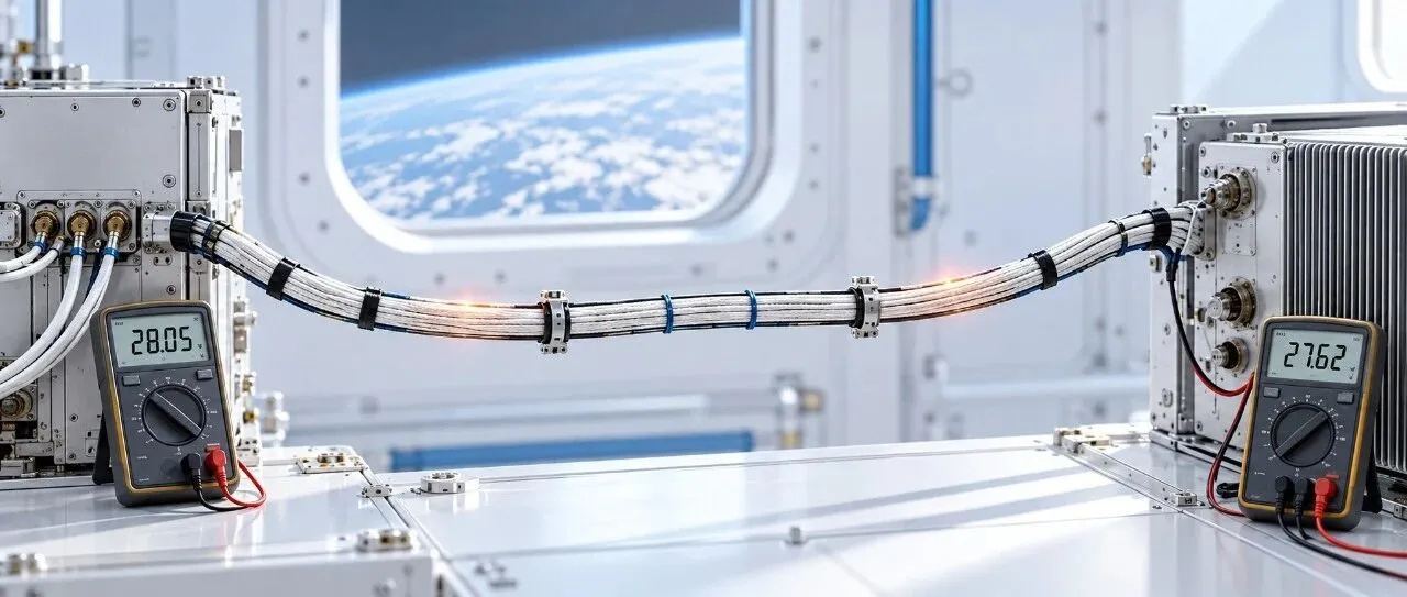
In a DC power branch operating steadily, the voltage between the source’s positive and return terminals is 26 V. At the equipment’s positive and return input terminals, it is only 24.71 V. Where did the missing 1.29 V go?
Check the current along this unbranched path, and something even more counterintuitive appears: it is 5 A at the beginning of the harness and still 5 A at the equipment input. If the wires have resistance, why does voltage drop while current does not progressively decrease along the way?
What Is Actually Lost When Voltage Drops?
To understand voltage drop, first distinguish voltage from current. Current is the amount of electric charge passing through a cross section per unit time: 1 A means 1 coulomb per second. Voltage is the electric potential difference between two points. It describes the corresponding change in electric potential energy per unit charge: 1 V equals 1 joule per coulomb. [1][2]
The 26 V across the source means that, for every coulomb of charge it drives through itself, the source supplies 26 J of electrical energy to the closed circuit. That energy is not a package carried by an individual electron; this is simply a way of accounting for the energy supplied and consumed per unit charge.
The 24.71 V between the equipment’s input terminals means that the equipment receives 24.71 J of electrical energy for every coulomb passing through it. The supply wire, return wire and connections together dissipate 1.29 J per coulomb, mainly as heat. That is the energy balance represented by the voltage drop.
Voltage-drop measurements must identify both measurement points. The supply and return wires can each account for part of the potential difference. To measure the voltage available to the equipment, connect the voltmeter across its positive and return input terminals. Checking only the supply side overlooks losses in the return path.
Why Does Resistance Cause a Voltage Drop?
Copper already contains free electrons that can move. Without an applied electric field, however, their thermal motion is random, producing no sustained net current. Once the circuit is connected, the source establishes a potential difference and an electric field forms inside the conductor. A small directional drift is superimposed on the electrons’ motion, producing current. Conventional current flows opposite to electron drift; engineering diagrams and voltage-drop directions normally follow conventional current. [2]
A real conductor is not an ideal material with zero resistance. Moving electrons are scattered by lattice vibrations, impurities and defects. The electric field continuously supplies energy to the charge carriers, and some of that energy becomes internal energy in the conductor—observed macroscopically as Joule heating. Maintaining current through a conductor with finite resistance therefore requires a finite electric field inside it.
Electric potential decreases in the direction of the electric field. If an electric field exists along a section of conductor, there must be a potential difference between its ends. For a resistive conductor, the relationship can be written as E = ρJ: a material with resistivity ρ carrying a current density J requires a corresponding electric field E. Integrating that field along the wire gives the familiar relationship ΔV = I × R under uniform, steady-state conditions.
This explains several intuitive results. A longer wire provides a longer path over which the electric field acts. A thinner conductor has a higher current density for the same current. Copper’s resistance also generally increases with temperature. Each of these factors increases the path resistance and therefore the voltage drop at a given current. If a conductor can be approximated as having zero resistance, the electric field needed to sustain steady current along it is also close to zero, and the wire itself has almost no voltage drop.
Why Doesn’t Current Decrease Along the Wire?
Voltage describes the energy change per coulomb between two points; current describes how many coulombs pass through a cross section each second. Wire heating consumes electrical energy, but it does not destroy charge. The question can be made more specific: why, if 5 coulombs enter one end every second, must 5 coulombs leave the other end?
Choose any two points along the wire and consider the section between them. If 5 coulombs enter from the left every second but only 4 coulombs leave from the right, that section accumulates 1 coulomb each second. This does not violate charge conservation, but it means charge is still accumulating. If the imbalance persists, the stored charge keeps increasing, which is inconsistent with the assumed steady state. [3][4]
When a circuit is first connected, charge can indeed redistribute briefly on wire surfaces and at the equipment input. These charges alter the local electric field, changing the conditions governing further charge flow. Once the circuit reaches steady state, the charge stored in the selected wire section no longer continuously increases or decreases. In one sentence:
Current entering a section − current leaving it = the rate of change of charge stored in that section.
In steady state, the rate of change is zero, so the currents entering and leaving are equal.
Thus, in this power branch with no branches or unintended leakage, the current is 5 A at the beginning of the supply wire, at the equipment input and throughout the return wire. The equipment draws electrical power, uses energy to operate and generates heat. But as long as this is its only supply-and-return path and operation is steady, charge must still return through the return wire. Likewise, wire resistance changes how electrical energy is distributed; it does not progressively consume the coulombs passing through each second.
Differences in wire thickness do not change this conclusion, even when the wires are made from the same material. A thinner section provides a smaller cross-sectional area for charge flow, so the charge carriers’ average drift velocity adjusts accordingly. In a thicker section, the drift velocity can be lower. The total charge passing through each section per second remains equal. “The current is the same” does not mean “the electrons move at the same speed everywhere.” [2]
Increasing wire resistance can reduce current, but it changes the operating point of the entire branch. For example, suppose both ends initially measure 5 A. After a higher-resistance wire is installed, a circuit with a resistive load might carry only 4 A. Both ends would then measure 4 A—not 5 A at the beginning and 4 A at the end. Equipment with a regulator adjusts its input current according to its operating behavior, while charge conservation still applies.
This equal-current relationship applies to steady operation along the same unbranched path. If the path splits into two branches, the current entering the junction equals the sum of the currents leaving through both branches. During startup or load switching, charge can briefly accumulate locally, so instantaneous readings at different points may differ. These situations still obey charge conservation. [3][4]
Estimating Voltage Drop: A Simple Calculation
Return to the hypothetical example at the beginning: the source voltage is 26 V and the steady-state branch current is 5 A. The total equivalent resistance at operating temperature of the supply wire, return wire and series components such as connectors and switches is 0.258 Ω, excluding the equipment load. Here, the path resistance is used directly without detailing wire size, length or temperature corrections.
Given: Rₚₐₜₕ = 0.258 Ω, I = 5 A
Voltage drop:
ΔV = I × Rₚₐₜₕ = 1.29 V
Equipment input voltage:
Vₑqᵤᵢₚₘₑₙₜ = 26 − 1.29 = 24.71 V
Power loss in the path:
Pₗₒₛₛ = I²Rₚₐₜₕ = 6.45 W
The source delivers 26 × 5 = 130 W, and the equipment receives 24.71 × 5 = 123.55 W. The remaining 6.45 W becomes heat in the wiring and connections. Current remains 5 A at both ends; what decreases is the power delivered to the equipment.
Voltage drop is directly related to wiring loss: at the same current, a larger voltage drop means more power is dissipated along the path. The resulting wire temperature rise also depends on how heat escapes and how long the current flows. Voltage drop alone cannot determine temperature rise.
In an actual design, path resistance must include the full lengths of both the supply and return wires, as well as connectors, crimped terminations, switches and other series elements. It must also reflect conductor temperature and aging conditions appropriate to the mission. Omitting the return path underestimates voltage drop.
Selecting Power Wires Requires More Than a Voltage-Drop Check
Whether a voltage drop is acceptable depends on the equipment interface. During a mission, the source may fall to its minimum bus voltage, while the equipment has a minimum permitted input voltage. The design must also retain the margin required by the project. The harness and all series connections can use only the voltage budget remaining between those limits. [5][6]

NASA’s Dragonfly mission: engineers connect an engineering model of the Integrated Electronics Module to the lander’s electrical harness. Credit: NASA/Johns Hopkins APL.
The wires must also carry current safely. At the same current, higher resistance produces more I²R heating. When multiple wires are bundled together, those near the center generally have greater difficulty dissipating heat. Wire gauge, insulation temperature rating, bundle size, continuous or intermittent operation, installation location and thermal environment all affect allowable current capacity. A universal rule such as “this cross-sectional area can carry this many amperes” cannot be applied without considering those conditions. [6][7]
Fault protection also affects wire selection. Following a short circuit, the wire must withstand fault heating until a fuse opens, a circuit breaker trips or current-limiting protection acts. The wire, protective devices and upstream source must be coordinated. Bend radius, terminations, dielectric withstand, electromagnetic compatibility, mass and routing space must also be checked. Increasing wire size reduces voltage drop and heating, but adds mass and integration costs.
This example addresses only steady-state voltage drop. During startup, pulsed operation and load switching, engineers must also check how equipment input voltage changes over time and whether protective devices operate as intended. [5]
The design calculations must ultimately be verified. With the harness de-energized and electronic equipment unsuitable for resistance testing appropriately isolated, resistance can be measured across clearly defined wire and termination paths. Low-resistance measurements often use a four-wire, or Kelvin, method to reduce the influence of test leads. Any contact interface being assessed must lie between the voltage-sensing points.
The circuit is then operated under the specified load conditions, recording source voltage, equipment input voltage, current and temperatures at critical connections. Where necessary, testing at operating temperature or under thermal-vacuum conditions verifies the electrical and thermal budgets. Continuity, insulation resistance, dielectric withstand and other project-required electrical and workmanship checks are assessed separately against the applicable requirements. [8]
Voltage Drop Is a Reduction in Energy per Unit Charge
Return to the opening example: the reduction from 26 V to 24.71 V means that 1.29 J per coulomb becomes heat in the harness and connections. The source continuously supplies energy, the electric field sustains directional current, and the real conductor dissipates part of that energy. Electric potential therefore decreases in the direction of conventional current.
Current remains 5 A throughout the same steady-state branch because the amount of charge passing each point per second has not changed. Wire resistance can change the current established in the circuit as a whole, but it does not consume current section by section.
A suitable spacecraft power branch must therefore answer four questions: can it safely carry the mission current, how much voltage remains at the equipment input, will fault protection act in time, and are the mass and system costs of reducing voltage drop acceptable? Voltage drop is only one requirement, but it is a key link between energy, temperature rise and the equipment interface.
Reliable satellite operation depends on getting details such as power distribution, equipment interfaces and verification right. Drawing on China’s expanding satellite manufacturing capacity, STARPATH GLOBAL helps international customers source competitively priced satellites, payloads and assembly, integration and testing (AIT) equipment suited to their mission requirements. If you are planning a satellite project or selecting hardware and test equipment, discuss your requirements with STARPATH GLOBAL to explore options that balance performance, integration needs and budget.
References
[1] OpenStax, University Physics Volume 2, 7.2, “Electric Potential and Potential Difference”; potential difference, changes in electric potential energy per unit charge, and 1 V = 1 J/C.
[2] OpenStax, University Physics Volume 2, 9.1–9.5; current, the model of electrical conduction in metals, resistivity, Ohm’s law, electrical energy and Joule heating.
[3] MIT OpenCourseWare, 6.071J Introduction to Electronics, Signals, and Measurement, “Resistive Circuit Analysis: Kirchhoff’s Laws,” 2006; Kirchhoff’s current and voltage laws and conservation relationships.
[4] OpenStax, University Physics Volume 2, 10.3, “Kirchhoff’s Rules”; current in series branches and voltage relationships around a circuit.
[5] ECSS-E-ST-20C Rev.2, Electrical and electronic, April 8, 2022; spacecraft power interfaces, source and load impedance, power distribution protection and harness inductance requirements.
[6] FAA AC 43.13-1B with Change 1, Chapter 11; voltage drop, current-carrying capacity, length, temperature, continuous and intermittent operation, and wire-bundle conditions in aircraft wire selection.
[7] NASA NTRS, Re-Architecting the NASA Wire Derating Approach, 2021; an interim report on wire and bundle temperature-rise research, cited for research context rather than as the basis for wire-selection limits in this article.
[8] ECSS-Q-ST-20-30C, Manufacturing and control of electrical harness, March 20, 2025; spacecraft electrical harness manufacturing, continuity, dielectric withstand, insulation resistance and process control.
[9] NASA Science, “Testing Dragonfly’s Electronic ‘Brain’,” page updated March 11, 2026; description of the photograph showing integration of the Dragonfly Integrated Electronics Module engineering model with the lander’s electrical harness.